
 Without a trick to help poor Arduino to restart SparkFun's 5V FTDI Basic breakout board could be more useful to me. To get hardware flow control from the board I did primitive fix: I made a bridge between pin 2 and 3 of FTDI232RL and cut off pin 2 on the board (see picture). After this kind of the Stone Age surgery connector's pin labeled as DTR actually carries RTS signal from FTDI232RL.
Monday, July 4, 2011
RTS on SparkFun's 5V FTDI Basic
Without a trick to help poor Arduino to restart SparkFun's 5V FTDI Basic breakout board could be more useful to me. To get hardware flow control from the board I did primitive fix: I made a bridge between pin 2 and 3 of FTDI232RL and cut off pin 2 on the board (see picture). After this kind of the Stone Age surgery connector's pin labeled as DTR actually carries RTS signal from FTDI232RL.
Friday, October 1, 2010
One new trick for an old dog
 Well... There is no much trick in the ten pin 0.05" (1.27mm) ARM JTAG/SWD connector, but it is definitely new for "an old dog" - LPC2103.
A few weeks ago I received several small 0.85 x 1.26" (23 x 32mm) LPC210x header boards from BatchPCB. OpenOCD version 0.3.1 with FTDI2232 based adapter does work with LPC2103 on the board via new tiny JTAG connector. However, the OpenOCD configuration file needs minor adjustment since the connector has no TRST pin. So the reset configuration should include
srst_only to let the OpenOCD know that TRST is not available.Thursday, April 1, 2010
CMSIS 2.0 Alpha
New Alpha version of CMSIS except adding Cortex-M4 support has replaced implementation of single assembly instruction functions by making them inline and moving code to dedicated header files (
core_cmFunc.h and core_cmInstr.h) in CoreSupport folder. Thanks ARM! Now I can utilize original CMSIS code in my projects instead of coping functions with modified names to an additional header file. Nevertheless, the definition of __INLINE for GCC compiler still does not enforce actual inlining of the code as I described in the previous post. Well. I hope it will be fixed in the final release.Monday, February 1, 2010
Using CMSIS with GCC
My interest in ARM Cortex-M3 based micros recently turned into some practical exercises with STM32-H103, GCC and Cortex Microcontroller Software Interface Standard (CMSIS) library. CMSIS is a useful set of definitions of Cortex-M0/M3 core architecture registers, data structures and interfaces to access core resources of a Cortex-M0/M3 based microcontroller. However, if you use GCC with CMSIS (v1.2.0 or v1.3.0) the definition of
__INLINE macro provided in core_cm3.h and core_cm0.h:#define __INLINE inlinedoes not force the compiler to actually inline the body of a function defined with
__INLINE attribute. To tell GCC to inline the define should be:#define __INLINE __attribute__((always_inline)) inlineFurthermore,
__get_xxx, __set_xxx, __LDREX, __STREX groups of a single assembly line functions implemented as a regular functions as oppose to inline functions. Change of these functions to inline style allowed two times improvement of the performance of certain fragments of my code.Sunday, June 21, 2009
My take on SST
My search of some sort of OS suitable for N1's on-board computer based on LPC2103 lead me to an article "Build a Super Simple Tasker" (SST). The article describes a "run-to-completion (RTC) prioritized, fully preemptive, deterministic real-time kernel". Although I like the simplicity of the idea I think that tight coupling between an event and its target task in SST implementation (see Listing 3) reduces flexibility of the kernel. The Observer pattern is commonly utilized by event propagation frameworks including frameworks designed by Mother Nature. Additionally, an Observer pattern based design would allow to create and destroy tasks during an application run time. With these thoughts in mind, I decided to put together my own implementation of the idea. Since the coding has been completed I am using this implementation in two unrelated projects and should confirm that RTC tasks fit pretty nicely into FSM oriented designs and single event queue implementation of the Observer pattern provides nice to have extra flexibility with minimal impact on performance.
Friday, May 29, 2009
Number one
 Number one (N1) is a robot which actually runs on a mobile phone. N1 has two parts: body and brain. The body consists of slightly modified chassis of N0 and tiny ARM® based computer which acts as brain spinal cord (BSC). N1 brain, located on a mobile phone and implemented as a Java ME program, connects to its BSC through Bluetooth®. There are some further technical details and photos on the robot's home page as well as a video which shows N1 equipped with infrared distance sensor in action.
Wednesday, May 20, 2009
Shrinkning Sharp GP2D120
 I needed to mount vertically Sharp GP2D120 on a micro servo. To reduce sensor's dimensions I decided to get rid of standard mounting holes and connector. Removing mounting holes is simple job while removing the connector involves cutting a part of sensor's PCB. After a bit of head scratching, I moved a resistor and replaced several wires routed on the PCB under connector. Finally, I drilled two tiny holes on the top part of the sensor's body for a wire which attaches the sensor to the servo.


Sunday, May 17, 2009
Mounting a PCB on LEGO
 I was looking for a while for a simple way of mounting a PCB on a construction made of LEGO® parts. Through-hole mount requires precise location of holes on a PCB and limits mounting flexibility as well as consumes a lot of valuable space on the board. The best solution to date for me is a three - four slightly modified LEGO® axle pins (gray pin is original and blue pin is modified) which hold edges of a PCB. The modification of four axle pins took about a minute thanks to DREMEL® rotary tool armed with 199 High Speed Cutter.

Thursday, October 30, 2008
Number zero
 Number zero (N0) is my first attempt to build a robot. This toy tractor is built from LEGO® Technic parts. (back view) The toy is driven by Java ME™ MIDlet on a mobile phone via Bluetooth (JSR82). Small board on the tractor comprise of BlueSMiRF Bluetooth class 1 module and Atmel's ATmega88 controller. Two 71427 LEGO® 9V motors are controlled by TI's SN754410 configured as a dual H-bridge.


Saturday, July 12, 2008
OpenOCD and FT2232's default VID/PID
I spent quite a bit of time today trying to get OpenOCD work with OpenOCD-USB Adapter on MacOSX (10.5). There are two hints which might save your time:
1) Since the adapter comes with no EEPROM, FT2232D uses default VID/PID (
0x0403/0x6010). If FTDIUSBSerialDriver (aka VCP) is installed on your machine, you will need to comment out or remove FT2232C_A section of driver's Info.plist file located at/System/Library/Extensions/FTDIUSBSerialDriver.kext/Contents/
This would prevent the FTDI VCP driver from conflicts with OpenOCD on attempt to use the port A of FT2232D on the adapter board. You also might want to reload the FTDI VCP driver after modification with following commands:
$sudo kextunload  /System/Library/Extensions/FTDIUSBSerialDriver.kext
kextunload: unload kext /System/Library/Extensions/FTDIUSBSerialDriver.kext succeeded
$sudo kextload -c /System/Library/Extensions/FTDIUSBSerialDriver.kext
kextload: /System/Library/Extensions/FTDIUSBSerialDriver.kext loaded successfully
2) Since the adapter comes with no EEPROM, you will need to use default device descriptor in OpenOCD configuration file:
ft2232_device_desc "Dual RS232 A"
Missing EEPROM on OpenOCD-USB Adapter board

As it turned out OpenOCD-USB Adapter does not have EEPROM which is on the adapter schematic (see the bottom of this page). The EEPROM chip (93LC46BT SOT-23-6) was removed from the board after manufacturing. It is clearly can be seen on the picture (6 pads on the right of USB connector). I guess, the EEPROM chip was removed because of an error on the adapter PCB (EEPROM's CLK and Vcc pins are swapped). The same adapter is also available form www.ic-board.de. So be aware of this defect.
Friday, July 11, 2008
5V for a target from OpenOCD USB Adapter
 I recently bought OpenOCD USB Adapter. The adapter arrived as a kit which comprises of the assembled adapter board, two IDC male connectors (ten and twenty pins) and one D-type 9 pin male connector.
One feature which is missing in this adapter from my point of view is an option to power up a target from USB. A USB port can provide up to 500 mA. The adapter should not consume more then 250 mA according to FT2232D datasheet. This would leave approximately 250 mA for a target board. For example, Olimex LPC2103 prototype header board would consume about a hundred mA.
Fortunately, there is a place on the adapter board for four pin header right behind D-type serial connector. Two pins in the center are serial's TTL TX and RX and pins on both sides are Ground and +5V straight from USB's Vbus. (Note, there is no ferrite bead on the adapter board.) I assembled a little board with MOSFET (FDN302P) to control power output. I used schematic of "Bus Powered Circuit with Power Control" (Figure 12) from FT2232D datasheet. The most challenging for me was to solder a wire to PWREN# pin (41) of FT2232D. The chip comes in the LQFP-48 package with leads on a 0.5mm pitch. Finally, since I do not need standard serial interface and only two pins in the second row of the serial connector are utilized, I decided to put a two pin polarized header in the first row to serve as a power connector for a target.
Well... As it turned out when OpenOCD (see update below about version 0.2.0) initializes interface FT2232 pulls PWREN# pin to high level for several hundred mS. This switches power off for the target. Meanwhile, OpenOCD attempts to communicate to the powered off target. I had to add a one second delay in
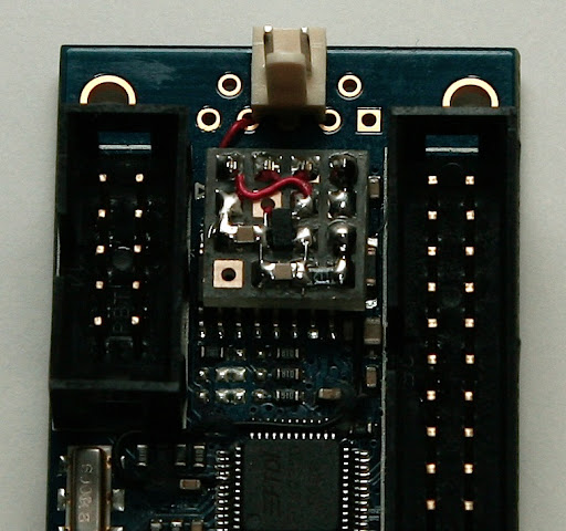
Well... As it turned out when OpenOCD (see update below about version 0.2.0) initializes interface FT2232 pulls PWREN# pin to high level for several hundred mS. This switches power off for the target. Meanwhile, OpenOCD attempts to communicate to the powered off target. I had to add a one second delay in
openocd.c between jtag_interface_init and jtag_init calls to make the modification work.UPDATE: OpenOCD version 0.2.0 seems to fix the issue above. I was able to flash and debug code on Olimex STM32-H103 board powered from the JTAG adapter.
Subscribe to:
Posts (Atom)